Part Number:MSP430FR5969
Hello,
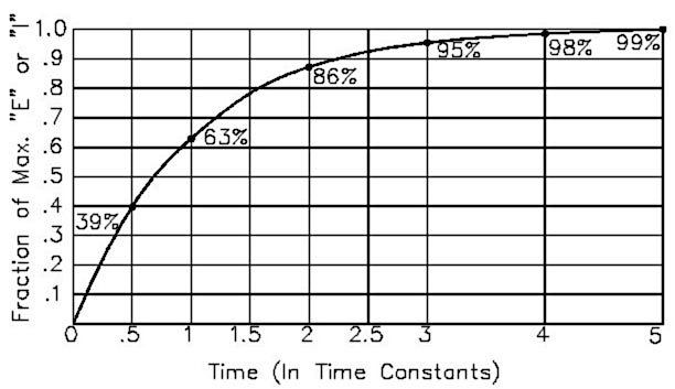
I am working on finding the resistor value of RC circuit. My idea was to start charging the RC circuit until (Tau~=RC) at 63 % of full voltage, and calculating the elapsed time , and from the reference capacitor we can get the value of the resistor.
I wrote the following code, however, what I get was not precise. The main problem I know it is with the timer, Can someone help me to modify my timer initialization to make precise measurements.
Thank you a lot
/*
 * This code is to measure resistor by charging and discharging capacitor
 * using one general timer
 * */
#include <msp430.h>
#include <stdio.h>
static unsigned int intervals=0; // Count number of 50,000 counts

/**
 * main.c
 */
void main(void)
{
    float StartTime=0;
    float ElapsedTime=0;
    float ResistorKohm,RefCapacitorNF=100;// capacitor in nano
    WDTCTL = WDTPW | WDTHOLD;	// stop watchdog timer
    PM5CTL0 = ~LOCKLPM5;        //unlock the GPIO pins

    //set the clock
    CSCTL0_H = 0xA5;
    CSCTL1 |= DCOFSEL_6;              // Set max. DCO setting = 8MHz
    CSCTL2 = SELA__VLOCLK + SELS_3 + SELM_3;
    CSCTL3 = DIVA__1 + DIVS__1 + DIVM__1;

    //Setting the timer for counting
    TA0CCR0 = 40000;       // 40000 * 0.125us = 5000us = 5msec, where 1/8MHZ=0.125us
    TA0CTL = TASSEL__SMCLK + MC__UP;    // Set SMCLK, UP mode
    TA0CCTL0 = CCIE;       // Enable interrupt for Timer_0
    _BIS_SR(GIE);          // Activate interrupts previously enabled


    //Setting up the pins
    P1DIR |= BIT3; // Set P1.3 as output to charge capacitor
    P1OUT &= ~BIT3; // Clear port1
    P1SEL1 |= BIT5; // Configure P1.5 for ADC
    P1SEL0 |= BIT5;

    // Configure ADC12
    ADC12CTL0 = ADC12SHT0_2 | ADC12ON; // Sampling time, S&H=16, ADC12 on
    ADC12CTL1 = ADC12SHP; // Use sampling timer
    ADC12CTL2 |= ADC12RES_2; // 12-bit conversion results
    ADC12MCTL0 |=ADC12INCH_5; // A5 ADC input select(P1.5)

    while(1)
    {
        ADC12CTL0 |= ADC12ENC; // Enable conversion
        ADC12CTL0 |= ADC12SC;// Start conversion
        P1OUT|=BIT3;
        StartTime=((intervals*40000)+TA0R)*0.125;
        while(ADC12MEM0 < 2889)
        {
            ADC12CTL0 |= ADC12SC;// Start conversion
        } // the value is 63.2% of full ADC range =2889
        ElapsedTime=(((intervals*40000)+TA0R)*0.125)-StartTime;
        ResistorKohm=ElapsedTime/RefCapacitorNF;

        printf("\n this is start time: %2.2f",StartTime);
        printf("\n this is elapsedtime: %2.2f",ElapsedTime);
        printf("\n the resistor : %8.3f",ResistorKohm);


        P1OUT &= ~BIT3;
        __delay_cycles(1000000);
    }

}


//************************************************************************
// Timer0 Interrupt Service Routine
//************************************************************************
#pragma vector=TIMER0_A0_VECTOR
__interrupt void Timer0_ISR (void)
{

    intervals = intervals + 1; // Update number of TA0CCR0 counts
}