Quantcast
Channel: MSP low-power microcontroller forum - Recent Threads
Viewing all 22007 articles
Browse latest View live

CCS: Conversion from float to unsigned interger-16

$
0
0

Tool/software: Code Composer Studio

As, I am working CCS V_8 version and deveolping code for MSP432P401R. I am facing a strange problem regarding overflow. As I have my project chain (ADC-DSP-DAC) in my complete project, I am working to implement a digital bandpass filter on MSP432 of the order of 46th by using floating point feature of controller. ADC input range is (0-2.5V) and I am expecting output range same for DAC but the problem is that when I increased input value more than 2.38V Then it leads to an overflow issue. By changing offset vale on signal generator, this issue can be tackeld up to some limit but it is not a professional solution. By googling, i read some articles regarding data type conversions and followed the given procedure (i.e. int (float+0.5)) but it is not helping me. As, my question is more about c programming but I think It has relation with CCS also.

Overflow is occuring due to last values of output when some values are becoming less than zero.Can you please help me to eliminate this overflow issue ??

Note: I have attached the pictures of output  with overflow and without overflow alongside the specific part of code too. Every possible suggestion is highly appreciated.

This two picture are taking at the input of step response to the filter.

AdcInputVoltage = AdcValueDigits*2.5f/16384.0f;
     filteredf_output = SincFilter(AdcInputVoltage);
    /* if (filteredf_output<0){ DacValueDigits = (uint16_t)(( filteredf_output* 65536.0f/4.096f)+0.5);
     }
     else {DacValueDigits= (uint16_t)(( filteredf_output* 65536.0f/4.096f));
    } */
     DacValueDigits = (uint16_t)(( filteredf_output* 65536.0f/4.096f)+.5);
     //DacValueDigits = ((uint16_t)(( filteredf_output* 65536.0f/4.096f)+32678.5))-32677;

Regards,

Hasan Nawaz


CCS/MSP430G2553: 4 Digit 7 Segment Clock

$
0
0

Part Number:MSP430G2553

Tool/software: Code Composer Studio

Hello!

I have a trouble with my MSP.

Display's kathodes have direct connection to uC. Only Anodes have resistors.|
Problem: Timer doesn't count.

After upload a soft, there are four digits with all leds on (except dots) - there are four eights like : 8 8 8 8.
Nothing happened at all.

Under Debug session I can see, that program stops on while(1)...
I was trying many different codes, but still no effect.
I have no warnings at all, no troubles, no problems.

What is wrong with code?

Thanks in advance for help.

DETAILS:
Connection (Common anodes A-5649 display) looks like:

P1.0 - segm. A
P1.1 - segm. B
P1.2 - segm. C
P1.3 - Button - useless now...
P1.4 - segm. D
P1.5 - segm. E
P1.6 - segm. F
P1.7 - segm. G

P2.0 - Digit 0    //via resistor 220 ohm
P2.1 - Digit 1    //via resistor 220 ohm
P2.2 - Digit 2    //via resistor 220 ohm
P2.3 - Digit 3    //via resistor 220 ohm
P2.4 - segm. DP

CODE:

#include <msp430.h>

#define a 0x01           //00 0000 0000 0001
#define b 0x02           //00 0000 0000 0010
#define c 0x04           //00 0000 0000 0100
#define d 0x10           //00 0000 0000 1000
#define e 0x20           //00 0000 0001 0000
#define f 0x40           //00 0000 0010 0000
#define g 0x80           //00 0001 0000 0000
#define Dig_1  0x01   //P2.0
#define Dig_2  0x02   //P2.1
#define Dig_3  0x04   //P2.2
#define Dig_4  0x08   //P2.3
#define DP     0x10   //P2.4
//#define S2     0x20   //Button 2 P2.5
//#define S1     0x03   //Button 1 P1.3

int display_min[]={a+b+c+d+e+f, b+c, a+b+d+e+g, a+b+c+d+g, b+c+f+g, a+c+d+f+g, a+c+d+e+f+g, a+b+c, a+b+c+d+e+f+g, a+b+c+d+f+g};
int display_hour[]={a+b+c+d+e+f, b+c, a+b+d+e+g, a+b+c+d+g, b+c+f+g, a+c+d+f+g, a+c+d+e+f+g, a+b+c, a+b+c+d+e+f+g, a+b+c+d+f+g};

//clock variables
volatile unsigned int j;
volatile unsigned int TI_second = 0;
volatile unsigned int TI_minute = 0;
volatile unsigned int TI_hour = 0;
volatile unsigned int LoopCtr1;
volatile unsigned int dig_num = 0;
unsigned int flag_dp = 0x01;

void Get_time(void)
    {
       j++;
      if (j==20)   //50mS * 20 = 1sec.
        {
          j=0;
         // P2OUT ^= DP;
          TI_second++;

          flag_dp = 1;
          if (TI_second==60)
            {
              TI_second = 0;
              TI_minute++;

              if (TI_minute==60)
               {
                 TI_minute = 0;
                 TI_hour++;

                if (TI_hour==24)
                  {
                    TI_hour = 0;
                  }
               }
            }
        }
    }


void Display_time(void)
    {
      switch( dig_num )
      {
        case 0:
          {
            P1OUT = display_min[TI_minute/10];    //load first digit for minutes
            P2OUT |= BIT0;   //set   dig#0
            P2OUT &= ~0x0E;  //clear dig#1, 2, 3
            dig_num = 1;
          }
          break;
		  
       case 1:
         {
			P1OUT = display_min[TI_minute%10];    //load second digit for minutes
			P2OUT |= BIT1;   //set dig#1
			P2OUT &= ~0x0D;  //clear dig#0, 2, 3
                if(flag_dp == 1)
					{
						flag_dp = 0;
						P2OUT ^= DP;
					}

			dig_num = 2;
         }
         break;

      case 2:
        {
			P1OUT = display_hour[TI_hour/10];    //load first digit for hours
			P2OUT |= BIT2;   //set dig#2
			P2OUT &= ~0x0B;  //clear dig#0, 1, 3
			dig_num = 3;
        }
        break;

      case 3:
        {
			P1OUT = display_hour[TI_hour%10];    //load second digit for hours
            P2OUT |= BIT3;   //set P2.3 - dig#3
			P2OUT &= ~0x07;  //clear dig#0, 1, 2
			dig_num = 0;
        }
        break;
      }
    }

int main(void)
{
      //initialization
      WDTCTL = WDTPW + WDTHOLD;     // Stop watchdog timer

       //----mcu clock settings------------------------------------------------------
      DCOCTL=0x00;
	  BCSCTL1=0xC0;
      BCSCTL2=0xC0;            //MCLK source = LFXT1CLK
      BCSCTL1 = XT2OFF + XTS + DIVA_0; // f/8
      BCSCTL2 = SELM_3 | SELS | DIVS_3;

      //----Ports settings----------------------------------------------------------
      P1OUT = 0x00;
      P2OUT = 0x1F;
      P1DIR = 0xF7;   // Set P1 Output dir Exclude Button S1
      P2DIR = 0x1F;   // Set P2 Output dir Exclude Button S2


      //----TimerA settings---------------------------------------------------------
      TA0CCTL1 |= CCIE;                // CCR0 interrupt enabled
      TA0CCTL2 |= CCIE;                // CCR1 interrupt enabled
      TA0CTL = TASSEL_1 + ID_3 + MC_2 + TAIE;  // TimerA = ACLK!!!, 1:8, upmode, int enable
      TA0CCR1 =  50000;
      TA0CCR2 =  5000;

    //---Interrupts settings--------------------------------------------------------
      _EINT();
	  
    //---Variables settings---------------------------------------------------------
      dig_num = 0;
      //_BIS_SR(CPUOFF + GIE);               // Enter LPM0 w/ interrupt
      while(1)
      {}  // Infinity loop 
}   // end main

// Timer 0 A1 interrupt service routine
#pragma vector = TIMER0_A1_VECTOR
__interrupt void TIMER0_A1_ISR( void )
{
switch( TAIV )
    {
        case  2:     // CCR1
			{
				TA0CCTL1 &= ~CCIFG;
				Get_time();
				TA0CCR1 += 50000;    // Add Offset to CCR1
			}
            break;
			
        case  4:    // CCR2
            {
				TA0CCTL2 &= ~CCIFG;
				Display_time();
				TA0CCR2 += 5000;
            }
            break;

        case 10: 
			break;
      }
}

CCS/MSP430G2553: Jumping to app via custom bootloader

$
0
0

Part Number:MSP430G2553

Tool/software: Code Composer Studio

Hi there,

I'm trying to make a custom bootloader for the MSP430G2553 with my own implementation of serial comm. But to do that, first I need to know how to jump from bootloader to user application.

I know how to to that in TM4C microprocessors; by modifying the .cmd file like this

and then jumping from bootloader like this

void Jmp_2App(uint_fast32_t ui32StartAddr)
{
    //define the vect table to the beginning of app in flash
    HWREG(NVIC_VTABLE) = ui32StartAddr;

    //Load stack pointer from app vect table
    __asm("    ldr     r1, [r0]\n"
            "    mov     sp, r1\n");

    //Load initial program counter from app vect table and branch to app entry point
    //e ramifica para o ponto de entrada do aplicativo
    __asm("    ldr     r0, [r0, #4]\n"
            "    bx      r0\n");
}

But the MSP430 seems quite different. I can alter the FLASH location but not the RESET. I did some reading, but it's unclear how to make a new reset vector and how to jump to the app address. Any help on the subject?

Regards,

Helder

MSP430FR5994: MSP430 Power Up time from cold start

$
0
0

Part Number:MSP430FR5994

Hello All,

I am currently evaluating the MSP430FR5994 chip for use and need to verify power up time from a cold start.  Per the data sheet, it specifies that nominal is .5ms, and max is 1ms (data sheet, section 5.12.4).  My tests show differently and was wondering if any know a way to test to get such results.  (not sure I can change the clock source prior to my GPIO pin going high, that is about the 3rd line in my test app)

My setup is as follows:

  1. using the LauncPad Dev board MSP-EXP430FR5994
  2. Using the bare bones "BlinkLed" project, modify it to init a specific GPIO on start and drive high
  3. Using an oscilloscope, connect probes to this pin, the 3.3v supply, and RST pin on the dev board
  4. Trigger scope by either
    1. Power up the board, triggering the scope on the rising edge of the GPIO.
    2. Leave board powered, press reset button

(basically, on cold start, 3.3 and RST go HIGH at the same time)

In both 4.a and 4.b, the time from RST high or 3.3 High to the GPIO High is about 1.7ms.  Our application requires very fast wake-up times, and saving a ms will help a lot..

Thanks,

-mike

Code Snippet:

int main(void) {

    volatile uint32_t i;

    // Stop watchdog timer
    WDT_A_hold(WDT_A_BASE);

    // Set P4.4 to output direction
    GPIO_setAsOutputPin(
       GPIO_PORT_P4,
       GPIO_PIN4
       );

    GPIO_setOutputLowOnPin(GPIO_PORT_P4,GPIO_PIN4); //init to 0

    GPIO_setOutputHighOnPin(GPIO_PORT_P4,GPIO_PIN4);//drive high - oscilloscope trigger

    // Board initialization
    Init_GPIO();

    GPIO_setOutputHighOnPin(GPIO_PORT_P4,GPIO_PIN4); //drive high again, init gpio will reset to low

    FRAMCtl_A_configureWaitStateControl(FRAMCTL_A_ACCESS_TIME_CYCLES_1);
    Init_Clock();  //16MHz DCO

    // Set P1.0 to output direction
    GPIO_setAsOutputPin(
        GPIO_PORT_P1,
        GPIO_PIN0
        );

    // Set P1.0 to output direction
    GPIO_setAsOutputPin(
        GPIO_PORT_P4,
        GPIO_PIN4
        );

    // Disable the GPIO power-on default high-impedance mode
    // to activate previously configured port settings
    //PMM_unlockLPM5();

    while(1)
    {
        // Toggle P1.0 output
        GPIO_toggleOutputOnPin(
            GPIO_PORT_P1,
			GPIO_PIN0
			);

        //GPIO_toggleOutputOnPin(
        //            GPIO_PORT_P4,
        //            GPIO_PIN4
        //            );

        // Delay
        for(i=1000000; i>0; i--);
    }
}

MSP430FR2632: Looking for i2c host code to program MSP430FR via bootloader (BSL)

$
0
0

Part Number:MSP430FR2632

Hello,

I've seen a couple of host-side code samples for updating MSP430 using the bootloader via UART, but not for i2c. Can someone point me to an i2c example?

Thanks, Hector

CCS/MSP430FR2355: Libraries for rf communication

$
0
0

Part Number:MSP430FR2355

Tool/software: Code Composer Studio

I'm trying to connect an RF transceiver (Linx NT Series Transceiver, TRM-900-NT) for RF communication to the MSP430 device, I wanted to know if there are libraries that might be helpful here. The transceiver supports uart communication, if that helps in the answer. I essentially just want to be able to send a sine wave or a data value of 1 (1 bit or byte, it doesn't matter) and receive a signal that has some data embedded in it. I'm unsure if I must implement the handshaking as a state machine and build everything from scratch or if there are pre-existing functions I could use. 

I tried to search online but didn't find anything particularly useful. Any help, or a prod in the right direction would be greatly appreciated. Please let me know if you need any more information. Thanks!

MSP430G2553: How does the PMM handle voltage above 3.6V?

$
0
0

Part Number:MSP430G2553

Hello All,

Thanks for reading.  I have a system that is using MSP430G2553 and is running above the recommended 3.6V power supply.  I am curious about how the Power Managment Module / Supply Voltage Supervisor actually handle when the DVcc is above 3.6V?  Does it set a flag?  Does it draw extra power?

I've read the datasheet for PMM / SVS but it does not mention this.   

Thanks for your insights.

MSP432P401R: I2C bus keeps busy after MASTER sending STOP

$
0
0

Part Number:MSP432P401R

I need to read back a bunch of registers from a sensor, but I can read only the first.

The following loop (where I am repeatedly reading the same register for simplicity) does not work as after fetching the first byte it gets stuck waiting for the bus to be available again:

while(i < sizeof(settings)) { // Wait for STOP to be sent while(I2C_masterIsStopSent(CLIM_I2C)); // Wait for bus to be available while(I2C_isBusBusy(CLIM_I2C)); // Set master as transmitter I2C_setMode(CLIM_I2C, CLIM_I2C_TRANSMIT_MODE); // Clear receive interrupt flag and the shift-register one I2C_clearInterruptFlag(CLIM_I2C, EUSCI_B_I2C_BIT9_POSITION_INTERRUPT); // Send start and slave address, plus 'write' bit, followed by register address I2C_masterSendMultiByteStart(CLIM_I2C, LPS22HB_WHO_AM_I_ADDR); // Wait until register address has been successfully sent to the shift register while(!I2C_getInterruptStatus(CLIM_I2C, EUSCI_B_I2C_BIT9_POSITION_INTERRUPT)); // Set to receive mode, send restart, stop and retrieve byte settings_p[i] = I2C_masterReceiveSingleByte(CLIM_I2C); // Increment index i++; }

Please, any hints, anyone?

MSP430Ware install on MAC failed with " “MSP430Ware_setup” is damaged and can’t be opened."

$
0
0

Hi,

I downloaded the MSP430Ware for Mac from:

Once downloaded, I opened the file and get:

The below image is my Computers basic information.

Would like to use the MSP430Ware, but for now not able too.

Regards,

Caleb

MSP430FR2433: about clock accuracy

$
0
0

Part Number:MSP430FR2433

Hi,

I have questions about clock of MSP430FR2433.

Q1: The performance at 16 Mhz is shown in Table 5-5 of the data sheet. Is there a difference in characteristics when 1MHz?


Q2: What is the jitter of REFO? (This is not shown in the data sheet.)


Best Regards,
H.U

MSP430F5152: MSP430F5152 gives Unknown device error while programming

$
0
0

Part Number:MSP430F5152

Dear All,

I am trying to program MSP430F5152 on my own hardware but it gives Unknown device error on Uniflash tool through MSP-FET430UIF.

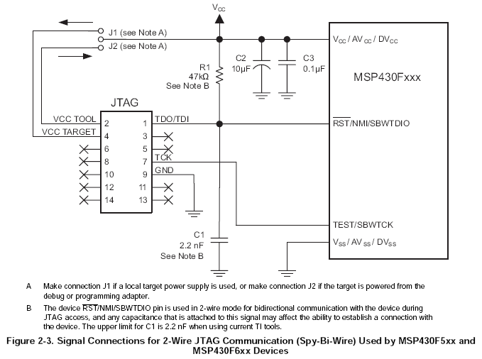
In hardware JTAG signal connection is in 2 wire (Spy-Bi-wire) and same as suggested in datasheet.

Even I tried to program after removing C1 2.2nF but still giving same error. Cable length of FRC to program is of 4 to 5 inch only.

Is it MSP-FET430UIF automatically switch from 4 wire to 2 wire Jtag communication or need to do some changes in hardware of MSP-FET430UIF.

Please anyone can help to resolve me this issue.

MSP430F1121: By MSP-FET430UIF able to program but with MSP-FET Flash Emulation Tool(Black plastic body) not

$
0
0

Part Number:MSP430F1121

I am facing issue while programming MSP430F1121A IC.


Dear All,

Is this any difference between two programmer MSP-FET430UIF and latest MSP-FET Flash Emulation Tool(Black plastic body)?

When I program through MSP-FET430UIF programmer and given power to MCU by programmer only than it program IC MSP430F1121A in one shot.

But while programming IC through MSP-FET Flash Emulation Tool(Black plastic body) in same way by giving power to IC through

programmer only than it give error as Unknown device. Why?

My board IC MSP430F1121A current consumption by programmer is max 40mA. And as per datasheet MSP-FET430UIF and latest MSP-FET Flash Emulation Tool both can able to give up to 100mA.

Can any one help me for this.

Regards,

Mahendra Rana

MSP430FR2633: MSP-CAPT-FR2633 Development Kit works abnormally when powered on at 2.15V

$
0
0

Part Number:MSP430FR2633

I tested low power consumption with MSP-CAPT-FR2633 Development Kit ,and the development board used the default software.

When the standby power is adjusted from 3.0V to 2.0, the standby power consumption can reach about 3UA. At this time, the FR2633 can work normally. 

when the board is directly powered  on at 2.15V, the current is always running within 500-900UA.  It seems that MSP430 has not been working properly, how to solve it?

MSP430FR2422: Writing information memory from BSL

$
0
0

Part Number:MSP430FR2422

Hi,

I'm trying to write the information memory in the device from the BSL. This always fails. My question is is this even possible from the BSL?

Kind regards,

Johan

energia healp

$
0
0

i am working in energia 1.8.7E21 with msp432P401R i have some error message 

the error is 1. Error compilling for Board RED  Launchpad w/ msp432EMT(48MHz)

2.file does not exist in a gaiben filder


MSP430F2272: Differences among lots

$
0
0

Part Number:MSP430F2272

Dear all,

one of my AA is asking if there have been any changes in the MSP430F2272IRHAT specifically in the following lots:

CGEF G4
A9X1 G4
ATY8 G4

Can you please verify ?

regards,

Domenico

CCS: How to pair the transmitting end and receiving end on the MSP430F2274

$
0
0

Tool/software: Code Composer Studio

I am working with the MSP430F2274 on CCS Cloud. I am having trouble finding a reference for a pairing code.

MSP430F2619: IBIS models

$
0
0

Part Number:MSP430F2619

Team, 

My customer has the following question: 

I'm trying to do signal integrity analysis on my circuit card.  We have the MSP430F2619S using I2C, SPI, JTAG, Interrupts, BSL, generic IO on it.  There isn't a model for that part.  What can I use to simulate the drivers and receivers?  Even if you have a buffer reference that's close enough?  Thanks.

 Regards,

Aaron

MSP430G2152: PW and RSA package correlation

$
0
0

Part Number:MSP430G2152

I have just completed a prototype design using the MSP430G2152 in the PW package (TSSOP-14).  The application is generating two PWM signals using TimerA0 on TA0.1 and TA0.2.  On the PW package I chose to route these signals to pins #4 and #6 respectively.  I'm just starting the artwork for the PCB layout but I would like to change the package to the RSA (QFN-16).  Looking at the device datasheet (SLAS722G.pdf), page 3, I noticed that the RSA package is not listing TA0.2 as an available multiplexing option for pin #5.  I'm hoping this is just a 'typo' or was intentionally omitted due to lack of printable space on this page?

Note, page 41 illustrates the P1.4 schematic pin.  TA0.2 is listed as an available option and I don't see any footnotes regarding possible package differences.  So I'm suspecting this option is available.

Thanks for the help.

Bill

MSP432E401Y: Cannot receive multicast (PTP) packets

$
0
0

Part Number:MSP432E401Y

Hello,

I have a working LwIP application on the MSP432E401Y, and I'm trying to get IEEE 1588 / PTP working using PTPd. I am unable to receive multicast UDP traffic and don't know what else to do. I can see the EMAC LED flashing once per second when my switch sends PTP packets. When I turn off PTP on the switch, the LED stops blinking once per second. So, I think the MSP432E4 PHY is receiving the packets but they are not getting through the MAC frame filter. I have placed a printf in the low-level LwIP UDP-processing function udp_input(), in the file udp.c. This shows that the LwIP application gets passed some data when I send a UDP packet to the microcontroller's static IP address (192.168.127.2), but I see no such printf called when it should be receiving multicast UDP packets.

So far I have tried all combinations of enabling and disabling EMAC_FRMFILTER_HASH_AND_PERFECT, EMAC_FRMFILTER_PASS_MULTICAST, and EMAC_FRMFILTER_PROMISCUOUS in EMACFrameFilterSet() in msp432e4if.c. But I haven't figured out why the microcontroller doesn't pass PTP packets to the application. I have also EMAC_TS_MAC_FILTER_DISABLE set in EMACTimestampConfigSet(), but that macro expands to zero so it is the same as the SDK default.

Is there some bug in the MAC which would make it filter out multicast traffic addressed to 224.0.1.129 or 224.0.0.107, ports 319-320?

Thanks for any help you can provide,

Paul

Viewing all 22007 articles
Browse latest View live


<script src="https://jsc.adskeeper.com/r/s/rssing.com.1596347.js" async> </script>