Part Number: MSP430F6726A
Hi,
Can we continue to display what was displayed in active mode even during LPM3.0?
Regards, Rei
Part Number: MSP430F6726A
Hi,
Can we continue to display what was displayed in active mode even during LPM3.0?
Regards, Rei
Part Number: MSP430FR5043
Tool/software: Code Composer Studio
hi
I tested the ZDF and TOF using the MSP430FR5043, ZDF and TOF are unstable.ZDF data is shown below. what is the problem?

Part Number: MSP432P401R
Hi
I use MSP432P401R devices as the hosts for the SBW communication with the target MSP430G2553,and software examples is MSP432Host_SBW_MSP430 folder in
the slaa754.
I used CCS7.1.0 to programming, I found if the image file more than 10KB would firmware upgrade failed. it would be stuck.
I also replace MSP432P401R device with beaglebone black to be hosts, software examples same as usual.
I use beaglebone black and find If the image file is less than 4KB, it can be success, but if the image file is more than 4KB, it failed. The file more than 4KB example
can erase successful but write failed, because the PSA CRC and the PSA value shifted out from the target deviceis different.I want to know how to get thePSA
value shifted out from the target device.

Thanks
Yi-ting
Part Number: MSP430FR2533
Hello,
I'm reading BOR section in page of 26 in Datasheet.
But I can't understand about BOR operation.
Is my following understanding correct?
Only If DVCC drops below (VBOR, safe), and kept low longer than (tBOR, safe) before it reaches VSVSH+, safe BOR is generated.
In safe BOR is being generated(after tBORsafe from at the time DVCC drops below VBORsafe), Device is in BOR reset state until DVCC reaches VSVSH+.
And I have three question.
1.How does the device measure tBOR time? (In the state of DVCC of 0.1V, logic such as counters in the device should not operate)
2.What is the trigger of Power Cycle Reset?
3.What is the difference between Power Cycle Reset, SVS Reset, BOR Reset and safe BOR in terms of the device state?
Regards,
U-SK
Part Number: MSP430FR2533
Hello,
The dimension between MSP430FR2533 and DC-DC converter is only 100mm.
Is it possible to cause any trouble to touch sensing of MSP430FR2533 due to the switching frequency of DC-DC converter (ex. RF noise)?
Regards,
U-SK
Hi Team,
I have a customer that is looking for a Microcontroller with the fastest startup time from power off to an ADC read.
The application is for gunshot detection. All of their electronics will be off until their sensor detects the gunshot.
They saw a competitor product with 3ms start-up time. Do we have a device faster than this?
Thanks.
Jonathan
Part Number: MSP430I2041
I have an MSP430i2041 board using the first 3 A/D channels, with
the 4th channel's inputs shorted together and grounded.
I need a simultaneous sample from all three channels 5000 times
per second, so I am constrained to use Oversampling Ratio 32.
This results in 8000 sample-set results per second. This is
fine with me, because I actually WANT to sample faster than I use
without averaging. (Yes, this is unusual, but I want to do this
to be less susceptible to periodic noise.)
What I DON'T want to do is suffer an interrupt for each A/D sample
set. I want the ONLY interrupt in my system to be the periodic
timer that tells me to return a sample every 1/5000th of a second.
How to do this? One surefire way would be to start a single A/D
conversion (on the group of three channels) every 1/5000th of a
second and then just poll for the IFG bit on the Master Channel
and then read and report the results (via UART). This would
introduce a latency of 125 microseconds (1/8000th of a second)
waiting for the A/D conversion but I could live with that.
A better way might be to run continuous conversions on the A/D
converter, and just "grab" a sample set every 1/5000th of a
second. The problem with this is that I cannot tell from the
documentation how to GUARANTEE that I get a simultaneous set
of three samples every time (short of suffering an interrupt
and reading/storing the samples 8000 times per second, and
locking out interrupts 5000 times per second while I read the
stored conversion from memory). I see a pathological scenario
where the A/D converter updates one of the SD24MEMx result
registers WHILE I am trying to read the last SET of results.
Since Plan A above really is surefire, that's what I'm going to
implement and just suffer the 125 uS latency. However, I thought
I'd run this by y'all to gather some opinions.
-eNick
Part Number: MSP430F5438A-EP
Hi,
Good day.
Our customer is requesting the certificate of volatility for MSP430F5438AMPZREP that identifies the type of memory it contain, if the parts are volatile or non-volatile, and the method suggested for clearing the memory for this part.
Thank you.
Regards,
Carlo
Part Number: MSP430F5529
Hi Experts,
Recently I started working on EPD* Extension Kit Generation 2 with TI Launchpad MSP430F5529LP But there in User Guide I didn't found any guide to compile the code in IAR. If anyone can help it will be helpful and also be appreciated.There I only saw for Code Composer Studio.
Thanks & Regards,
Part Number: MSP430F2418
Hi,
I am using MSO430F2418 for my project. I am sending Hello world message to Bluetooth module via UART pins. Also I need to set pin P2.3 to high to reset the Bluetooth. Unfortunately Im unable to set that perticuler pin to high. When I check the voltage at Reset pin of Bluetooth it is low.
I am just copying my code here. Can someone look into it and tell me the solution. Thank you.
#include <stdio.h>
#include <msp430.h>


const char string[] = { "Hello World\r\n" };
unsigned int i;

int main(void){
  WDTCTL = WDTPW + WDTHOLD;                 // Stop WDT

  if (CALBC1_1MHZ==0xFF)                    // If calibration constant erased
  {
    while(1);                               // do not load, trap CPU!!
  }

  DCOCTL = 0;                               // Select lowest DCOx and MODx settings
  BCSCTL1 = CALBC1_1MHZ;                    // Set DCO
  DCOCTL = CALDCO_1MHZ;
   P2DIR|=0x08;
   P2OUT|=0x08;
  P3SEL = 0x30;                             // P3.4,5 = USCI_A0 TXD/RXD
  UCA0CTL1 |= UCSSEL_3;                     // SMCLK
  UCA0BR0 = 8;                              // 1MHz 115200
  UCA0BR1 = 0;                              // 1MHz 115200
  UCA0MCTL = UCBRS2 + UCBRS1;               // Modulation UCBRSx = 5
  UCA0CTL1 &= ~UCSWRST;                     // **Initialize USCI state machine**
 // IE2 |= UCA0RXIE;                          // Enable USCI_A0 RX interrupt
  IE2 |= UCA0TXIE;
  __bis_SR_register(LPM0_bits + GIE);       // Enter LPM0, interrupts enabled
}

#pragma vector=USCIAB0TX_VECTOR
__interrupt void USCI0TX_ISR(void)

{
        UCA0TXBUF = string[i++]; // TX next character
       if (i == sizeof string - 1){ // TX over?
        IE2 &= ~UCA0TXIE; // Disable USCI_A0 TX interrupt
       _delay_cycles(1000000);
        i = 0;
        IE2 |= UCA0TXIE; // Enable USCI_A0 TX interrupt
       }
 }
Part Number: MSP432E401Y
Dear support,
I have an application using the CANIP, the Ethernet and some I2C and UART serial ports. As long as the code is being executed from the CCS using the debugger attached (XDS110), everything works as expected. Once I remove the debugger or press and external push-button, the system starts up as before with one exception. The signal on the CANIP is completely messed up. All the other interfaces do work as expected except the CANIP. Without knowing I guess it might have to do something with the clocking network on the chip.
The application is using "simplelink_msp432e4_sdk_3_20_00_10" and "FreeRTOSv10.2.1" in TI-CCS 9.1.... using the TI-Compiler.
The init sequence for the canip peripheral is shown below:
unsigned char bbcInitMSP432CANIP(int iCANIP) {
UNSIGNED8 ret = 0;
if( 1 == iCANIP) { // CAN controller CAN1
/* Enable the clock to the GPIO Port B and wait for it to be ready */
MAP_SysCtlPeripheralEnable(SYSCTL_PERIPH_GPIOB);
while(!(MAP_SysCtlPeripheralReady(SYSCTL_PERIPH_GPIOB)))
{/* wait for peripheral ready */
}
/* Enable CAN1 */
MAP_SysCtlPeripheralEnable(SYSCTL_PERIPH_CAN1);
while(!(MAP_SysCtlPeripheralReady(SYSCTL_PERIPH_CAN1)))
{/* wait for peripheral ready */
}
/* Configure GPIO Pins for CAN mode */
MAP_GPIOPinConfigure(GPIO_PB0_CAN1RX);
MAP_GPIOPinConfigure(GPIO_PB1_CAN1TX);
MAP_GPIOPinTypeCAN(GPIO_PORTB_BASE, GPIO_PIN_0 | GPIO_PIN_1);
....
As mentioned it always works using the debugger. It never works without it. Is there a way to check if the system clock has been stabilized before proceeding?
br
Markus
Hello team,
my customer is looking for an MCU which has an integrated Ethernet controller and a footprint smaller than 6x6mm, do we have any device that could suit these needs?
Thank you in advance for your support!
Best regards,
Adrian
Part Number: MSP430FR6047
Hi,
I would like to know if I could use the wM-Bus stack combining MSP430FR6047 with CC112x transceivers, and if it would be free-of-charge" and "royalty-free", as with others modules.
As said on this link, "The stack is provided “free-of-charge” and royalty-free when used with CC1310 and CC1350."
Also "NOTE: Multiple other TI hardware platforms, including the two-chip solution of the MSP430 + CC112x and CC120x high performance transceivers are also supported, specifically the 868 and 169 MHz bands."
Part Number: MSP430FR5969
Tool/software: Code Composer Studio
Hello,
The goal of my project is to make a programmable current sink from 0-1A using the PWM from the MSP430 and the intergrated 12 b ADC to complete the control loop.
I have recently been able to recreate my simulation (attached) and my code below to output the correct voltage on my INA250 to measure the current throught my load resistor.
I have a question regarding reading the voltage from the INA250 to my ADC. When I run the code independently with an external DC power supply, the ADC is able to read the voltage on the pin.
Though when I connect the output of the INA 250 EVM to the input of the ADC (verified the voltage is correct using a DMM), the voltage is incorrect in ADCMEM0.
Pasted is my code as well as my TINA simulation for the external circuitry.
#include <msp430.h>
float ADC_val;
int Current_add;
float Voltage_Desired;
float Current_Set;
float Current_t;
float Duty_Cycle;
float Current_val;
int PWM_up;
float Voltage_val ;
float ADC(void)
{
WDTCTL = WDTPW | WDTHOLD; // Stop WDT
// GPIO Setup
P4OUT &= ~BIT6; // Clear LED to start
P4DIR |= BIT6; // Set P1.0/LED to output
P1SEL1 |= BIT5; // Configure P1.1 for ADC
P1SEL0 |= BIT5;
// Disable the GPIO power-on default high-impedance mode to activate
// previously configured port settings
PM5CTL0 &= ~LOCKLPM5;
// Configure ADC12
ADC12CTL0 = ADC12SHT0_2 | ADC12ON; // Sampling time, S&H=16, ADC12 on
ADC12CTL1 = ADC12SHP; // Use sampling timer
ADC12CTL2 |= ADC12RES_2; // 12-bit conversion results
ADC12MCTL0 |= ADC12INCH_5; // A1 ADC input select; Vref=AVCC
ADC12IER0 |= ADC12IE0; // Enable ADC conv complete interrupt
while (1)
{
__delay_cycles(5000);
ADC12CTL0 |= ADC12ENC | ADC12SC; // Start sampling/conversion
__bis_SR_register(LPM0_bits | GIE); // LPM0, ADC12_ISR will force exit
__no_operation(); // For debugger
}
}
int main(void)
{
WDTCTL = WDTPW | WDTHOLD; // Stop WDT
// Configure GPIO
P1DIR |= BIT0 | BIT1; // P1.0 and P1.1 output
P1SEL0 |= BIT0 | BIT1; // P1.0 and P1.1 options select
// P1IES |= 0x00;
// Disable the GPIO power-on default high-impedance mode to activate
// previously configured port settings
PM5CTL0 &= ~LOCKLPM5;
CSCTL0_H = CSKEY >> 8; // Unlock CS registers
CSCTL1 = DCOFSEL_6; // Set DCO = 8MHz
CSCTL2 = SELA__VLOCLK | SELS__DCOCLK | SELM__DCOCLK;// Set ACLK=VLO SMCLK=DCO
CSCTL3 = DIVA__2 | DIVS__2 | DIVM__2; // Set all dividers
CSCTL0_H = 0; // Lock CS registers
// Configure Timer0_A
TA0CCR0 = 2000; // PWM Period
TA0CCTL1 = OUTMOD_7; // CCR1 reset/set
TA0CCR1 = 666; // CCR1 PWM duty cycle
TA0CCTL0 = CCIE ; // CPC intetupt
TA0CTL = TASSEL__SMCLK | MC__UP | TACLR; // SMCLK, up mode, clear TAR
//__bis_SR_register(LPM0_bits); // Enter LPM0
ADC();
}
#if defined(__TI_COMPILER_VERSION__) || defined(__IAR_SYSTEMS_ICC__)
#pragma vector = ADC12_VECTOR
__interrupt void ADC12_ISR(void)
#elif defined(__GNUC__)
void __attribute__ ((interrupt(ADC12_VECTOR))) ADC12_ISR (void)
#else
#error Compiler not supported!
#endif
{
switch(__even_in_range(ADC12IV, ADC12IV_ADC12RDYIFG))
{
case ADC12IV_NONE: break; // Vector 0: No interrupt
case ADC12IV_ADC12OVIFG: break; // Vector 2: ADC12MEMx Overflow
case ADC12IV_ADC12TOVIFG: break; // Vector 4: Conversion time overflow
case ADC12IV_ADC12HIIFG: break; // Vector 6: ADC12BHI
case ADC12IV_ADC12LOIFG: break; // Vector 8: ADC12BLO
case ADC12IV_ADC12INIFG: break; // Vector 10: ADC12BIN
case ADC12IV_ADC12IFG0: // Vector 12: ADC12MEM0 Interrupt
Current_Set = .03125
;
Voltage_Desired = Current_Set *2;
ADC_val = ADC12MEM0;
Voltage_val = (ADC_val*3.6)/4096;
Current_val = Voltage_val/2;
Duty_Cycle = (Voltage_val*2000)/3;
if (Voltage_val != Voltage_Desired)
{
Duty_Cycle = (Voltage_Desired*2000) / 3;
}
else
{
Duty_Cycle = TA0CCR1;
}
TA0CCR1 = Duty_Cycle;
}
}
#if defined(__TI_COMPILER_VERSION__) || defined(__IAR_SYSTEMS_ICC__)
#pragma vector = TIMER0_A0_VECTOR
__interrupt void Timer0_A0_ISR (void)
#elif defined(__GNUC__)
void __attribute__ ((interrupt(TIMER0_A0_VECTOR))) Timer0_A0_ISR (void)
#else
#error Compiler not supported!
#endif
{
if (PWM_up == 1)
TA0CCR1 = x;
PWM_up = 0;
}
(Please visit the site to view this file)
Thank you for the support!
Connor Connaughton
Part Number: MSP430FR6972
Tool/software: TI C/C++ Compiler
MSP430FR6972 information FLASH: address: 1800-19ff, is this area ferroelectric?
Part Number: MSP430FR2155
Hi Experts,
We want to use msp430 as 8Mbps SPI master when MCLK or SMCLK is 24MHz. I tested SPI clock became 8Mbps by setting UCA0BR0 as 0x03 (24/3 = 8). In this case, the clock duty is 1:2. If a peer device can accept this duty, is this msp430 operation guaranteed? The data communication is bi-directional.
Regards,
Hisao Uchikoshi
Part Number: MSP430FR2522
Hello,
I have a question about CapTIvate electrodes.
Customers are making prototypes and conducting experiments.
A 10mm button and an 8mm button are implemented.
When common-mode noise is input,
The 8mm button is falsely detected than the 10mm button.
Does the influence of noise change depending on the size of CapTIvate electrodes?
If it changes, can you tell me the trend?
Regards,
Da
Part Number: CC430F6137
Dear TI team,
We are developing a product based on TI CC430F6137. Below is a snapshot of the device initialization routine which enables XT1 CLK that source from a 32.768KHZ watch crystal. In addition, the XT1_CLK is used as a reference signal to PLL/DCO and generate MCLK.
During the course of stepping through the initialization routine, we occasionally encountered a situation where MCU is trapped in a do-while loop (BOLD font) , because DCOFFG flag always set to 1, regardless of the fact that it is cleared in the loop. This situation happens once in a while when we rapidly switch on/off power to CC430F6137 for multiple times in a role. As soon as the device enters this state, resetting the device through system reset pin doesn't help as the MCU keeps on being trapped in the do-while loop. The only way to resolve the issue is to recycle the power to the MCU in a normal manner. Would you please review our initialization code and give us advice for any improvement that can be implemented to resolve the issue we experienced? Thank you.
Best regards,
Peter
MCU Clock Initialization routine
{
UCSCTL6 &= ~XCAP_3; //Clear XCAP value
UCSCTL6 |= XCAP_1; //Set XCAP value to 6pf
P5SEL |= (BIT0 | BIT1); /* set P5.0 & P5.1 for external source of XT1 */
__delay_cycles(375000);
UCSCTL3 &= ~SELREF_7; /* Set DCO FLL reference = XT1 */
UCSCTL4 |= SELA_2; /* Set ACLK = REFO */
__bis_SR_register(SCG0); /* Disable the FLL control loop */
UCSCTL0 = 0x0000; /* Set lowest possible DCOx, MODx */
UCSCTL1 = DCORSEL_5; /* Select DCO range 24MHz operation */
UCSCTL2 = FLLD_1 + 499; /* (499 + 1) * 32768 = 16384000Hz */
__bic_SR_register(SCG0); /* Enable the FLL control loop */
/* Worst-case settling time for the DCO when the DCO range bits have been
* changed is n x 32 x 32 x f_MCLK / f_FLL_reference.
* 32 x 32 x 16 MHz / 32,768 Hz = 500000 = MCLK cycles for DCO to settle
*/
__delay_cycles(500000); /* delay cycle is updated according to formula */
/* Loop until XT1,XT2 & DCO fault flag is cleared */
do
{
UCSCTL7 &= ~(XT2OFFG + XT1LFOFFG + DCOFFG) /* Clear XT2,XT1,DCO fault flags */
SFRIFG1 &= ~OFIFG; /* Clear fault flags */
}while (SFRIFG1&OFIFG); /* Test oscillator fault flag */
}
Part Number: MSP430G2955
Dear team,
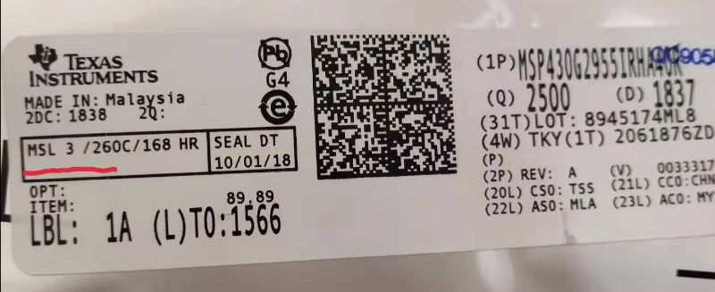
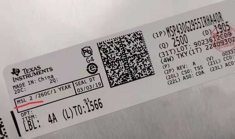
My customer bought two trays of MSP430G2955IRHA40R from Avnet. But they have different MSL level.
One of the two trays is made in China, the LOT number is 9023612CD9, the MSL rating is 2, the other is Malaysia, the LOT number is 8945174ML8, and the MSL rating is 3.
Is the MSL level different from the origin? Or is it related to production time? At what point did the material undergo a MSL level change?
Please help.

